


- Python2 round isn’t what you think
21 April 2025 19:45
The usual wisdom is that python2 “rounding of halfway cases was away from zero”. Does that mean that Python 2.7.12 (default, Mar 1 2021, 11:38:31) [GCC 5.4.0 20160609] on linux2 Type “help”, “copyright”, “credits” or “license” for more information. >>> round(100.215, 2) 100.22 Right ? Away from zero. Then, explain this: >>> round(2.675, 2) 2.67 The problem seems to come from the underlying floating point representation (no way to represent exactly 2.675 for example). Utterly annoying when porting code from python2 to python3, especially with a ton of tests that will break. By the way >>> round(56.805, 2) 56.8 >>> round(-2.675, 2) -2.67
- Current fall latency
7 August 2022 00:07
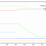
I’ve been fighting with instabilities in the MPPT algorithm for some time, and I’ve nailed it to the behavior of the system when the speed on the motors is reduced. You might remember that there is no battery on the Almabraxas 3.1 machine, the power coming from the PV panels has to be consumed at the time of its production, thus the MPPT regulation is performed by playing with the motors power settings. Stated another way, the power manager (the module executing the MPPT algorithm) looks for the maximum power point by increasing or reducing the “throttle” on the electric motors. The power manager runs at 100Hz. To work, it needs the current measurement to be more or less at this speed. To my surprise, when the throttle is cut (from ~20W on the working prototype), it takes about 300ms, for the current to go to zero. The only significant inductor being the motors themselves, it is possible that this corresponds to the release of the electromagnetic energy stored in the motors, although they are brushless, and the kinetic energy of the rotating blades. This is illustrated on the graph below. The red line is the voltage in V/10 units, the dotted green line is the value read by the MCU from the Hall effect current measurement circuit in arbitraty units, the continuous green line is the current in discrete step of 10mA used by the Power Manager (thus 70 on the scale = 700 mA), the “+” line is the throttle, in arbitrary linear units (thus 0 is 0). The other lines are irrelevant for now. The horizontal axis is the time, in MPPT ticks. Since it’s working at 100 Hz, each tick represents 10ms, thus for example 100ms take place between the 420 and 430 marks. At the beginning, the throttle is at some value at a stable regime. At time 440, we can see the throttle (the “+” line) set to 0. In 1 to 2 ticks (10-20 ms) the voltage (red line) jumps from 13.2V to about 14.2V, however we can see that the current takes 240ms to go to zero. This leads the MPPT algorithm to make erroneous decisions, as illustrated below. The legend is the same as before, except we now have the power (voltage x current) as a dark blue line, and the decision of the MPPT algorithm as an orange line. The decision is read as this: if the value is up, increase the throttle, and if the value is down decrease the throttle. Note that there is a security threshold if the voltage goes below 11V, the system considers there was a sudden drop in luminance, and shut down the motors to avoid them draining all the charges from the supercapacitors used to maintain power in the MCU. Please note that this particular version of the MPPT algorithm is based on power alone (thus the power manager plays with the throttle to maximize power, as previously indicated). At the beginning, we can see the power manager gradually increasing the throttle to extract more power from the power source. Note that in this case, this is not a real PV panel, but a bench PSU set with a maximum current so as to lower the voltage as an overcurrent precaution, in order to emulate the behavior of a solar panel. As the motors power increases, more and more current is drawn from power source, and the voltage slightly decreases. At time 103, the voltage hits the low limit, and the MCU set the throttle to 0, thus making the voltage jumps, but the current doesn’t fall immediately, leading to an increased measured power ! (same current, higher voltage = higher power), while the reading should be zero if the system had no inertia. The power manager believes it should draw more power, while it’s already drawing too much. A similar test conducted on a real PV panel leads to similar results. The problem could be fixed by making the power manager clock slower, thus giving time for the current to stabilize, but the idea is to have a fast reaction when there is a rapid change in lighting condition, so this is not my first choice.
- Almabraxas 3-1: power management strategy
21 January 2021 13:20
How do you manage power on a battery-less, solar-powered autonomous (ro-)boat ? Well, the power management part of the prototype is done and working for Almabraxas 3-1, so I guess I’ve finally landed on the strategy. The first point is that there is no battery in the Almabraxas roboats. If there is enough sun, they move. If there isn’t, they don’t. There are several reasons for that: If you want to cross an Ocean, with a 200W solar panel boat, this is a several months journey, with potentially hundreds or even thousands of charge-discharge cycles. Even though batteries have made significant progress in term of durability and number of charge-discharge cycles, I didn’t want to bet too much on it.By eliminating the battery, I felt I eliminated a possible point of failure (however, this point is amenable to discussion, see below).By putting the electricity into a battery, and then taking it out of the battery for propulsion, we lose 10-15% of energy in the process.I just wanted to try that way. I like the idea of a robot that has to sleep at night. MPPT We get more juice from our solar panels by using an MPPT algorithm, that is basically that we adjust the power drained from the solar panel to the available power. If we try to extract more power from the panel than is available, the solar panel reacts by lowering its voltage (part of the photovoltaic effect), thus we end with less power that is actually available. In a typical home photovoltaic installation, you get an MPPT module that will do this kind of processing, by delivering the requested power on one hand, and storing the excess energy in a battery. However, in the case of the Almabraxas boat, there’s no battery, by design. Thus, the system has to adapt the drawn power to the available power at any time, actually 1 hundreds times a second (100 Hz) in the case of Almabraxas. There are two power consumers on board, the computer (including sensors and telecommunication) and the thrusters. The computer doesn’t consume much power, around 5W, and we have little control over its consumption if we want to keep it running. Thus, the power consumption control is made by adjusting the power requested by the thrusters. This control is performed by the on-board computer (in a task called the power manager). As a matter of clear discussion, the computer board together with its various sensors is called the ABOC (Almabraxas Boat On-board Computer). Of course, to run the power manager task, ABOC needs to be up and running itself. UVLO Since at very low voltage, the MCU is not working and thus cannot drive the power consumption, the board is kept off at low voltage by a Schmitt trigger built from a few op amps. Need for a reserve (supercapacitor) I started with the idea of having no reserve at all, but it became very quickly clear that this wasn’t a reasonable idea: the processor is at risk to be in a brown state when there’s just enough energy to power it, even with a UVLO, leading to an unpredictable behavior. So there are a few (9 to be precise, but this is not very relevant) supercapacitors mounted in series to resist to 24V, providing about 10F of capacity. When there’s no sun and no power, this gives some time to the processor to wait some time until the sun may come backto put things in order (writing log to the flash memory ans putting everything in a low power state for example) while there’s still some juice. The cut-off voltage for the motor is set to ~11.5V measured by the MCU. The cut-off power for the processor is set to 5.7V, controlled by a Schmitt trigger. Given the consumption of the main board (the “ABOC”), this gives at least 400s of autonomy when power goes down. During that time, the processor does nothing except waiting for the power to come back. All systems (radio, GPS, log, etc…) are put in a sleep state. During the power-up stage, the hysteresis of the Schmitt trigger is such that the MCU is on when voltage is greater that ~11V. Thus, when powering up (with MCU off), the capacitor are charged while the voltage is below 11V, giving the backup time until 5.7V when the MCU is turned on. All voltage measurement are taken at the output of the PV diode. Starting only when enough power is available Not disturbing the MPPT with the capacitors bank Difficulty with the Schmitt trigger (Using voltage comparators) Putting it all together: the strategy
- MBED, FlashIAP, TDBStore and STM32F4 internal flash
15 March 2020 17:14

(Also: deriving your own class from SlicingBlockDevice) It wasn’t completely trivial to have all of them work together. Either the documentation doesn’t dig deep enough into some hidden assumptions, or I was just too dumb to find it. Anyway, the problem is as follows: I want to store configuration data (such as calibration values or the navplan) in the persistent memory of a robot. Very occasionally, the data has to be updated remotely in the field, but it’s mostly read. Power can fail at any time (it’s solar in my case), so the writing must be robust to power failure. Also, I need to add or change the list of stored parameters during development, while retaining the data already stored in the persistent memory at a former stage, so a bit more flexibility than simple addresses would be welcome, a key / values system would do the trick. Mbed 5 comes with a component that does exactly that: TDBStore. It works on a (string) key / value scheme. It’s resistant to power failure, that is, should power fail during a writing, the database won’t be updated, but it won’t be corrupted either. To do that, TDBStore needs to store two copies of the database: “in modification” and “committed” in some sense. The copies have to be contiguous (the second copy comes immediately after the first one). Beyond requiring twice as much room in the underlying storage, flash for example, this will become important at some point. Each copy is stored in an entire number of sectors. In this context, a sector is a contiguous block of memory that has to be erased all at once. And, of course, both copies must be of the same size. TDBStore in itself isn’t tied to a particular storage, we have to provide with some form of it, as an Mbed BlockDevice, such as an external flash, an internal memory block (volatile in that case), or the MCU internal flash. My MCU is the STM32F4, the STM32F446RE on a Nucleo board to be precise, which comes with 512KB of flash, and my program + bootloader uses only a fraction of it. This is why it’s interesting to store the data in the internal flash of the MCU, rather than an external SD Card / flash component which would be an additional potential point of failure. The structure of the flash memory in the STM32F446RE is the following: Sector #AddressSize (KB)00x080000001610x080040001620x080080001630x0800C0001640x080100006450x0802000012860x0804000012870x08060000128 Thus a total of 512KB in 8 sectors. As we can see from the addressing, the sectors are contiguous. In its internal memory, the STM32F446RE has the ability to write bytes one by one, while on SD cards it’s much more common to have to write an entire sector of 512 bytes or more at once. However the erase size is the entire sector, for example 128KB in the case of sectors 5 to 7, and a sector must be erased at least once before being used. First approach (program #1) Mbed puts your program at the beginning of the flash memory. The object code of my program is about 100KB. We get very quickly there when using some standard libraries, such as printf and other stuff, which quickly grow to a few dozens of kilobytes. The net result is that the first 5 sectors are used, and we’re left with 3 x 128 KB. “Hey, that’s more that I need”, you think. “Furthermore, it makes sense to put the database at the end of the flash, thus the address doesn’t have to change, given there’s enough room for both the .text segment and my database”. Now is the important point. When starting, TDBstore scans both copies of the database (you remember there were two of them, right ?) to determine which is the committed one and erase the other copy for a fresh start. Actually, it has an “erase as you go” algorithm to avoid taking too much time, since the MCU may be locked while erasing in some architecture. If we have a flash card with a 512 or 1KB sector which we can write and erase, this is all very well. But here the erase unit is the entire 128KB sector, and we need two of them !!! So all in all, with a naive first approach, we’ve to dedicate 256KB of our precious flash memory, which may be a lot. Okay, but this is a start. Here’s what it looks like: #include “mbed.h” #include <FlashIAPBlockDevice.h> #include <TDBStore.h> #include <flash_data.h> static DigitalOut led(LED1); static Serial pc(SERIAL_TX, SERIAL_RX, 115200); #define FIRST_DB_BLOCK (ADDR_FLASH_SECTOR_6) static FlashIAPBlockDevice full_flash(FIRST_DB_BLOCK, 256 * 1024); static TDBStore nvStore(&full_flash); static uint32_t val; int main() { full_flash.init(); int res = nvStore.init(); printf(“init result = %d\n”, res); res = nvStore.get(“_0000”, &val, sizeof(val)); printf(“get result = %d, value = %ld\n”, res, val); val += 1; res = nvStore.set(“_0000”, &val, sizeof(val), 0); printf(“set result = %d\n”, res); for(;;) { led = !led; wait_us(1000000); } } mbed_json.app Including the necessary components However, the code isn’t the end of the story. First, the FLASH and FLASHIAP components aren’t included by default in Mbed compilation, we’ve to tell it. This is done in mbed_json.app by putting target_feature.add and target.components_add directives. Partitioning the flash to protect your database from the linker Our code and initialized data (the .text segment) and the database share the same flash memory, so it’s a good idea to tell the linker not to overwrite the database. Mbed puts the .text segment at the beginning of the flash (this is why we put the databse at the end, remember ?). So all we have to do is to tell the linker not to use too much space, which is also done in mbed_app.json. In this first example, we’re using the last 2 128KB memory banks (256 KB), which leaves 256 KB for the .text segment (0x40000 in hex). We tell the linker not to use more by adding a target.restrict_size directive to mbed_app.json. Resulting mbed_app.json Given all that, here’s what we get: { …


Copyright © 2026 | WordPress Theme by MH Themes