
I’ve been fighting with instabilities in the MPPT algorithm for some time, and I’ve nailed it to the behavior of the system when the speed on the motors is reduced.
You might remember that there is no battery on the Almabraxas 3.1 machine, the power coming from the PV panels has to be consumed at the time of its production, thus the MPPT regulation is performed by playing with the motors power settings. Stated another way, the power manager (the module executing the MPPT algorithm) looks for the maximum power point by increasing or reducing the “throttle” on the electric motors.
The power manager runs at 100Hz. To work, it needs the current measurement to be more or less at this speed.
To my surprise, when the throttle is cut (from ~20W on the working prototype), it takes about 300ms, for the current to go to zero. The only significant inductor being the motors themselves, it is possible that this corresponds to the release of the electromagnetic energy stored in the motors, although they are brushless, and the kinetic energy of the rotating blades.
This is illustrated on the graph below.
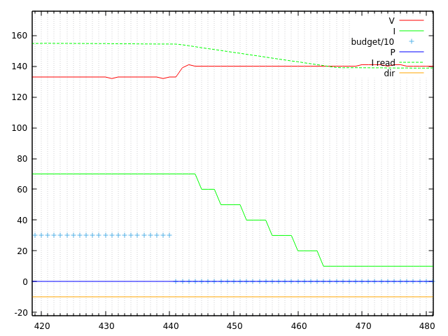
The red line is the voltage in V/10 units, the dotted green line is the value read by the MCU from the Hall effect current measurement circuit in arbitraty units, the continuous green line is the current in discrete step of 10mA used by the Power Manager (thus 70 on the scale = 700 mA), the “+” line is the throttle, in arbitrary linear units (thus 0 is 0). The other lines are irrelevant for now. The horizontal axis is the time, in MPPT ticks. Since it’s working at 100 Hz, each tick represents 10ms, thus for example 100ms take place between the 420 and 430 marks.
At the beginning, the throttle is at some value at a stable regime. At time 440, we can see the throttle (the “+” line) set to 0. In 1 to 2 ticks (10-20 ms) the voltage (red line) jumps from 13.2V to about 14.2V, however we can see that the current takes 240ms to go to zero.
This leads the MPPT algorithm to make erroneous decisions, as illustrated below.
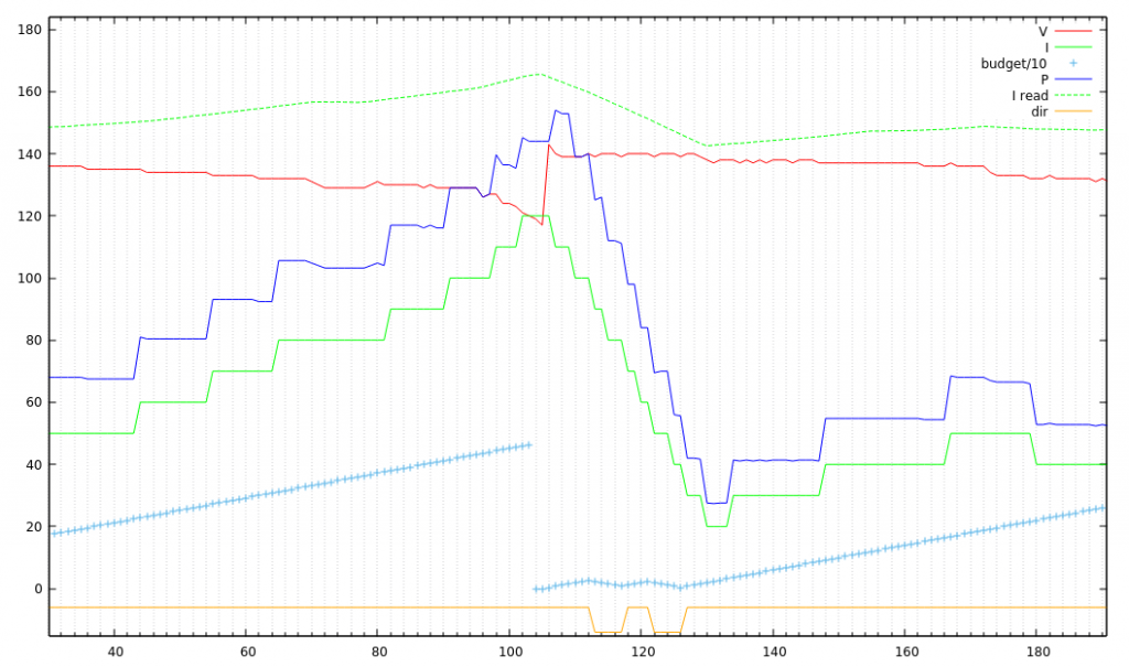
The legend is the same as before, except we now have the power (voltage x current) as a dark blue line, and the decision of the MPPT algorithm as an orange line. The decision is read as this: if the value is up, increase the throttle, and if the value is down decrease the throttle.
Note that there is a security threshold if the voltage goes below 11V, the system considers there was a sudden drop in luminance, and shut down the motors to avoid them draining all the charges from the supercapacitors used to maintain power in the MCU.
Please note that this particular version of the MPPT algorithm is based on power alone (thus the power manager plays with the throttle to maximize power, as previously indicated).
At the beginning, we can see the power manager gradually increasing the throttle to extract more power from the power source. Note that in this case, this is not a real PV panel, but a bench PSU set with a maximum current so as to lower the voltage as an overcurrent precaution, in order to emulate the behavior of a solar panel. As the motors power increases, more and more current is drawn from power source, and the voltage slightly decreases.
At time 103, the voltage hits the low limit, and the MCU set the throttle to 0, thus making the voltage jumps, but the current doesn’t fall immediately, leading to an increased measured power ! (same current, higher voltage = higher power), while the reading should be zero if the system had no inertia. The power manager believes it should draw more power, while it’s already drawing too much.
A similar test conducted on a real PV panel leads to similar results.
The problem could be fixed by making the power manager clock slower, thus giving time for the current to stabilize, but the idea is to have a fast reaction when there is a rapid change in lighting condition, so this is not my first choice.